
On my trip I have been through several pre-sales discussions on storage. Therefore I’m taking this opportunities to write up a series of postings deep diving into storage technologies. In this first section, we lay out the foundation of storage technology, from physical device to RAID, focusing on the concepts. Some contents are excerpts from Information Storage and Management.
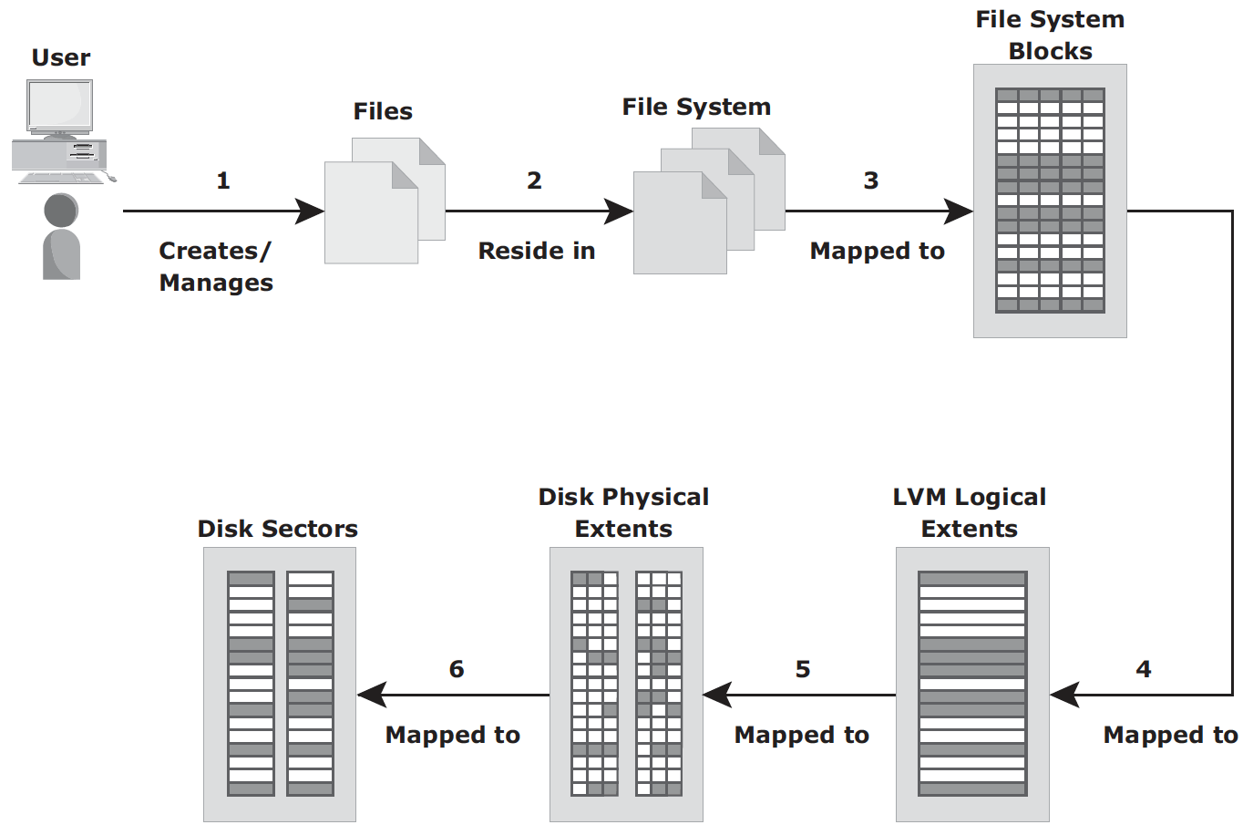
Volume Manager – In early days, a file system occupies the entire disk drive, and presents continuous disk blocks directly to operating systems. Logical Volume Manager (LVM) was then introduced to bring a layer of abstraction (logical volume) on top of disks. The layers are shown as follows:
With all these layers, a byte in user file maps to disk sectors through several layers:
File System – a hierarchical structure of files. It organizes data in a structural hierarchical manner. It includes files, directories as well as metadata. metadata must be consistent for the file system to be considered healthy. In Linux, metadata consists of:
- Superblock: important information about file system, e.g. type, creation and modification dates, size, mount status flag
- Inodes: a data structure that contains information associated with every file or directory
- list of data blocks free and in use
Host connects to storage through various Interface Protocols. Common interface protocols include:
- IDE/ATA and Serial ATA
- SCSI (Small Computer System Interface)
- FC (Fibre Channel)
- IP (Internet Protocol per se is a network protocol traditionally used for host-to-host traffic in the early days. In the virtualization era, it has become a viable option for host-to-storage communication. Examples are iSCSI and FCIP)
The most prevalent disk drive types are SSD (solid state drive) and HDD (hard disk driveA). SSD (solid state drive) is newer, flash-based technology. Without seek and rotational latencies they deliver a high number of IOPS with low response times. They are especially suited for applications with small block size and random-read workloads requiring constant latency <1ms.
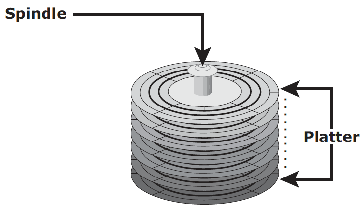
HDD is traditional and more cost effective. Its physical components are illustrated in the following two graphs:
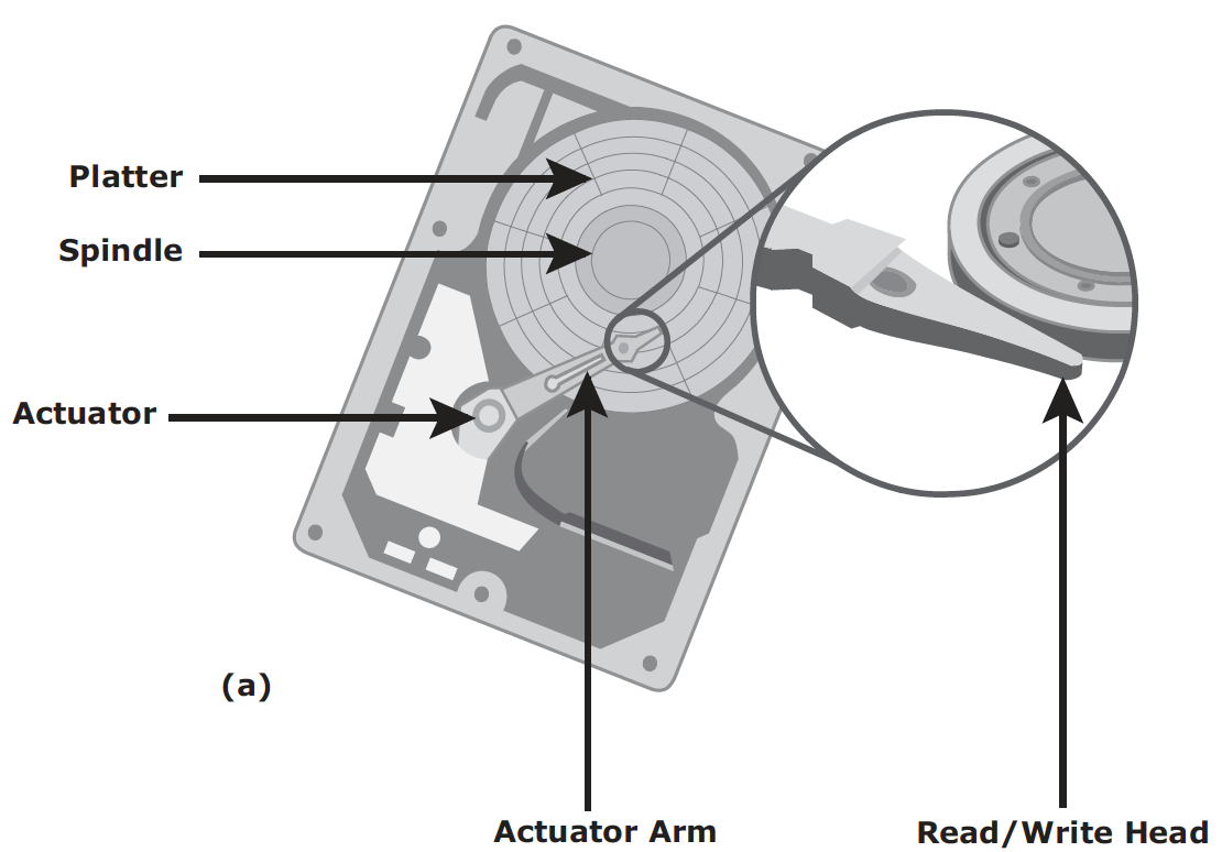
For HDD, disk service time (time taken by a disk to complete an I/O request) is determined by the following factors:
- Seek time (aka access time) describes the time taken to position the R/W heads across the platter with a radial movement (moving along the radius of the platter). In other words, it is the time taken to position and settle the arm and the head over the correct track.
- Rotation latency is the time taken by the platter to rotate and position the data under the R/W head. It depends on the rotation speed of the spindle and is measured in milliseconds.
- (Data) transfer rate is the average amount of data per unit time that the drive can deliver from disk controller to the HBA (on the host).
Zone Bit Recording – a mechanism to use disk efficiently by grouping tracks into zones based on their distance from the disk.
Logical Block Addressing (LBA) – disk controller translates LBA to a physical address (CHS, cylinder, head and sector). The host only needs to know the size of disk drive in terms of number of blocks. The logical blocks are mapped to physical sectors on a 1:1 basis
IO request processing – I/O controller is introduce to improve response time for I/O request, in this model, The I/O requests arrive at the controller at the rate generated by the application. This rate is also called the arrival rate. These requests are held in the I/O queue, and the I/O controller processes them one by one, as shown here:

The relationship between controller utilization and average response time is:
Average response time = Service time / (1 – Utilization)
where service time is the time taken by disk controller to service the I/O request. This results in a classic relation between response time and utilization, as plotted below:
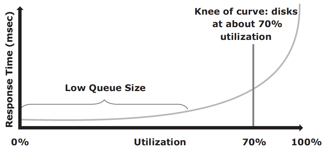
The graph indicates that the response time changes are nonlinear as the utilization increases. When the average queue sizes are low, the response time remains low. The response time increases slowly with added load on the queue and increases exponentially when the utilization exceeds 70 percent. Therefore, for performance-sensitive applications, it is common to utilize disks below their 70 percent of I/O serving capability.
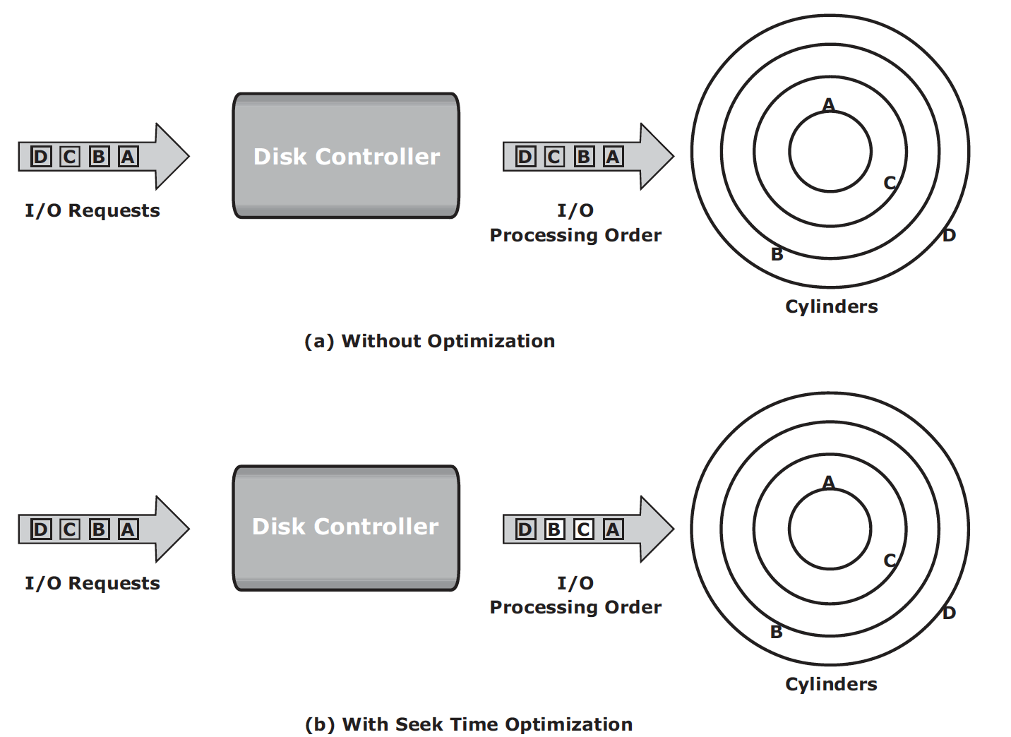
Command queuing is a technique implemented on modern disk drives that determines the execution order of received I/Os and reduces unnecessary drive-head movements to improve disk performance. When an I/O is received for execution at the disk controller, the command queuing algorithms assign a tag that defines a sequence in which the commands should be executed. With command queuing, commands are executed based on the organization of data on the disk, regardless of the order in which the commands are received. Below is an example:
RAID is a technology that leverages multiple drives as part of a set that provides data protection against drive failures. It may also improve performance by serving I/Os from multiple disks simultaneously. It is primarily used in HDD but SSD may still benefit from it. RAID may be implemented by software but hardware RAID with a controller is widespread. RAID is built on three basic techniques:
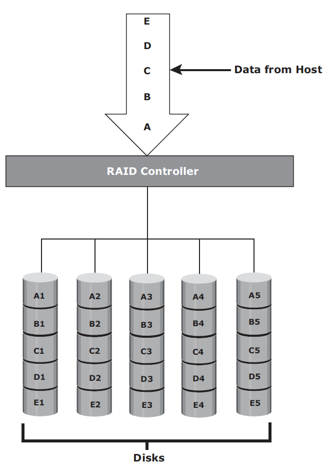
- Striping: spread data across multiple drives (more than one) to use the drives in parallel.
- Mirroring: same data is stored on two different disk drives, yielding two copies of the data.
- Parity: a method to protect striped data from disk drive failure without the cost of mirroring. An additional disk drive is added to hold parity, a mathematical construct that allows re-creation of the missing data.
Basic RAID levels are summarized here:
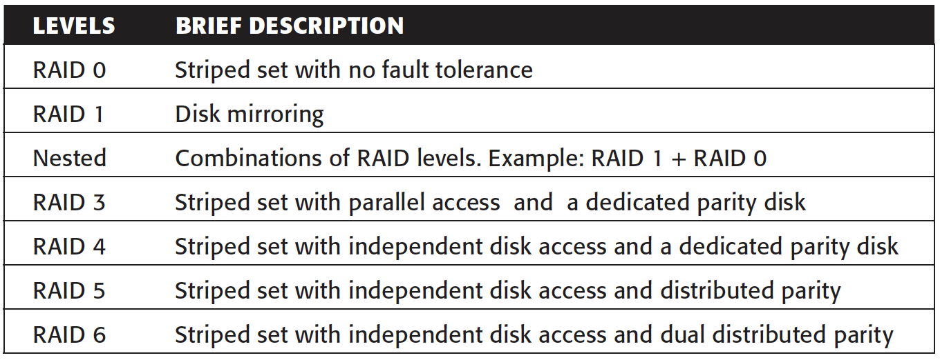
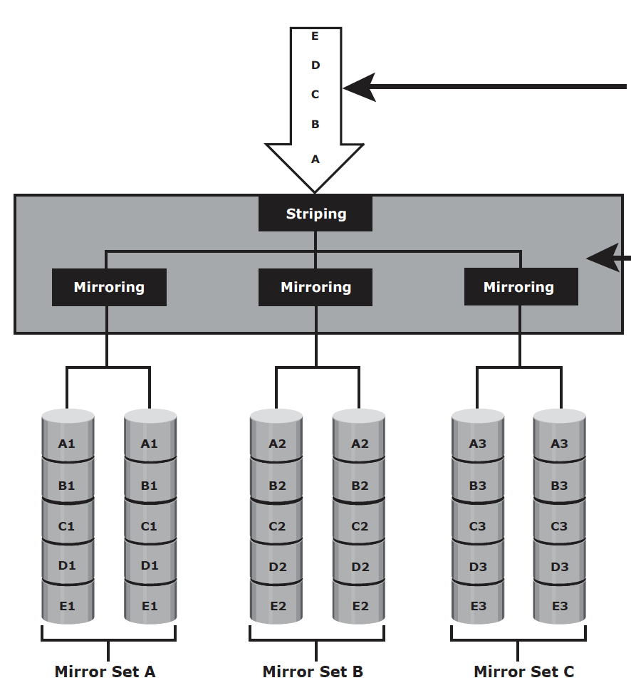
RAID 0, 1, 5 and 6 are pretty common in data centre operations. In addition to these levels above. If you hear RAID 1+0, 5+0 and RAID 6+0, they are called nested RAID. They are simply a RAID 0 on top of RAID1, RAID 5 and RAID 6, respectively.
RAID 0 – data striping technique utilizes full capacity of drives. Although it is a good option for applications that need high I/O throughput. It lacks data protection so it cannot drive application requiring high availability.
RAID 1 – mirroring technique ensures data duplication. In the event of disk failure, it introduces minimal impact to the disk array. It is suitable for applications that require high availability and cost is no constraint.
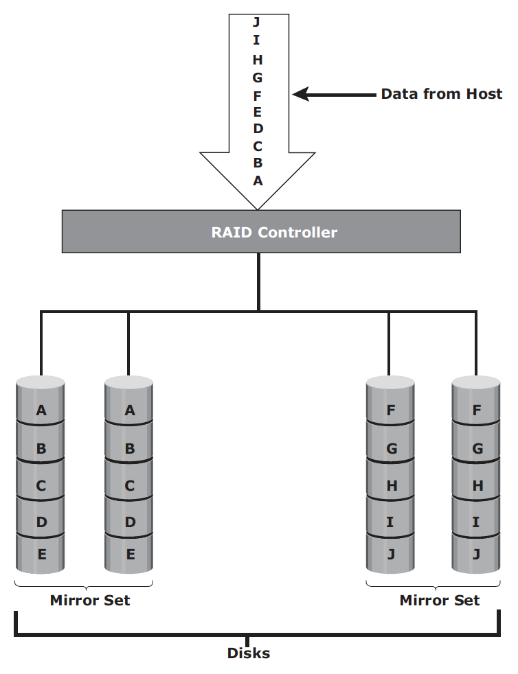
RAID 1+0 or RAID 10 – performs well for workloads with small, random, write-intensive I/Os. Some applications that benefit from RAID 1+0 include the following:
- High transaction rate Online Transaction Processing (OLTP)
- Large messaging installations
- Database applications with write intensive random access workloads
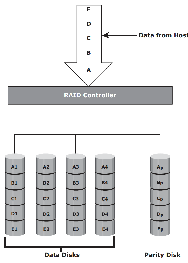
RAID 3 – RAID 3 stripes data for performance and uses parity for fault tolerance. the total disk space required is 1.25 times the size of the data disks. RAID 3 always reads and writes complete stripes of data across all disks because the drives operate in parallel. RAID 3 provides good performance for applications that involve large sequential data access, such as data backup or video streaming.
RAID 5 – RAID5 is similar to RAID 4 because it uses striping. The drives (strips) are also independently accessible. The difference between RAID 4 and RAID 5 is the parity location. In RAID 4, parity is written to a dedicated drive, creating a write bottleneck for the parity disk. In RAID 5, parity is distributed across all disks to overcome the write bottleneck of a dedicated parity disk.
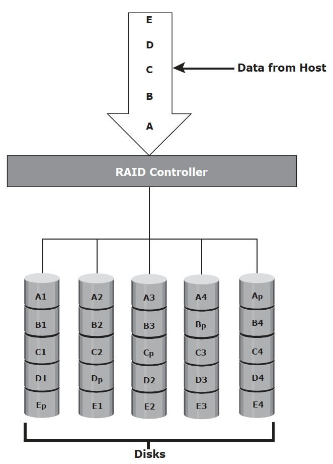
RAID 5 is good for random, read-intensive I/O applications and preferred for messaging, data mining, medium-performance media serving, and relational database management system (RDBMS) implementations, in which database administrators (DBAs) optimize data access.
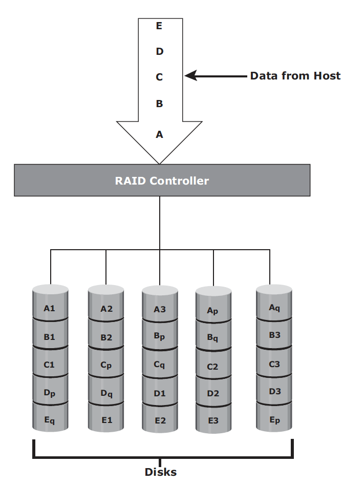
RAID 6 – works the same way as RAID 5, except that RAID 6 includes a second parity element to enable survival if two disk failures occur in a RAID set. The write penalty in RAID 6 is more than that in RAID 5; therefore, RAID 5 writes perform better than RAID 6. The rebuild operation in RAID 6 may take longer than that in RAID 5 due to the presence of two parity sets.
Intelligent Storage System involves cache as the core component. An intelligent storage system involves front end, cache, back end and physical disks, as shown here:
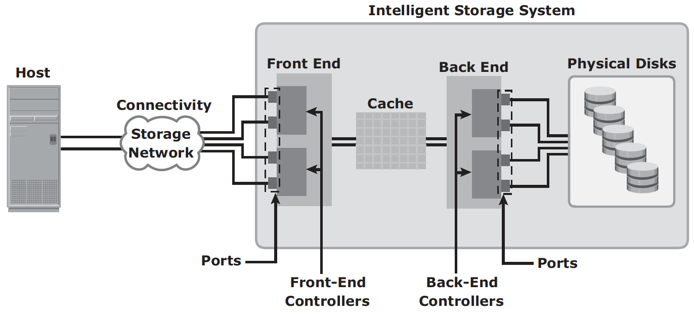
A variety of physical disk types and speed (e.g. mix of FC, SATA, SAS and flash) can be supported in a modern intelligent storage system. The front end provides the interface between the storage system and the host. It consists of ports and controllers, with redundancy. The back end provides an interface between cache and the physical disks. It consists of ports and controllers. For high data protection and high availability, storage systems are configured with dual controllers with multiple ports.
Cache improves storage system performance by isolating hosts from mechanical delays associated with hard disks. In intelligent storage system, read and write are first attempted on cache.
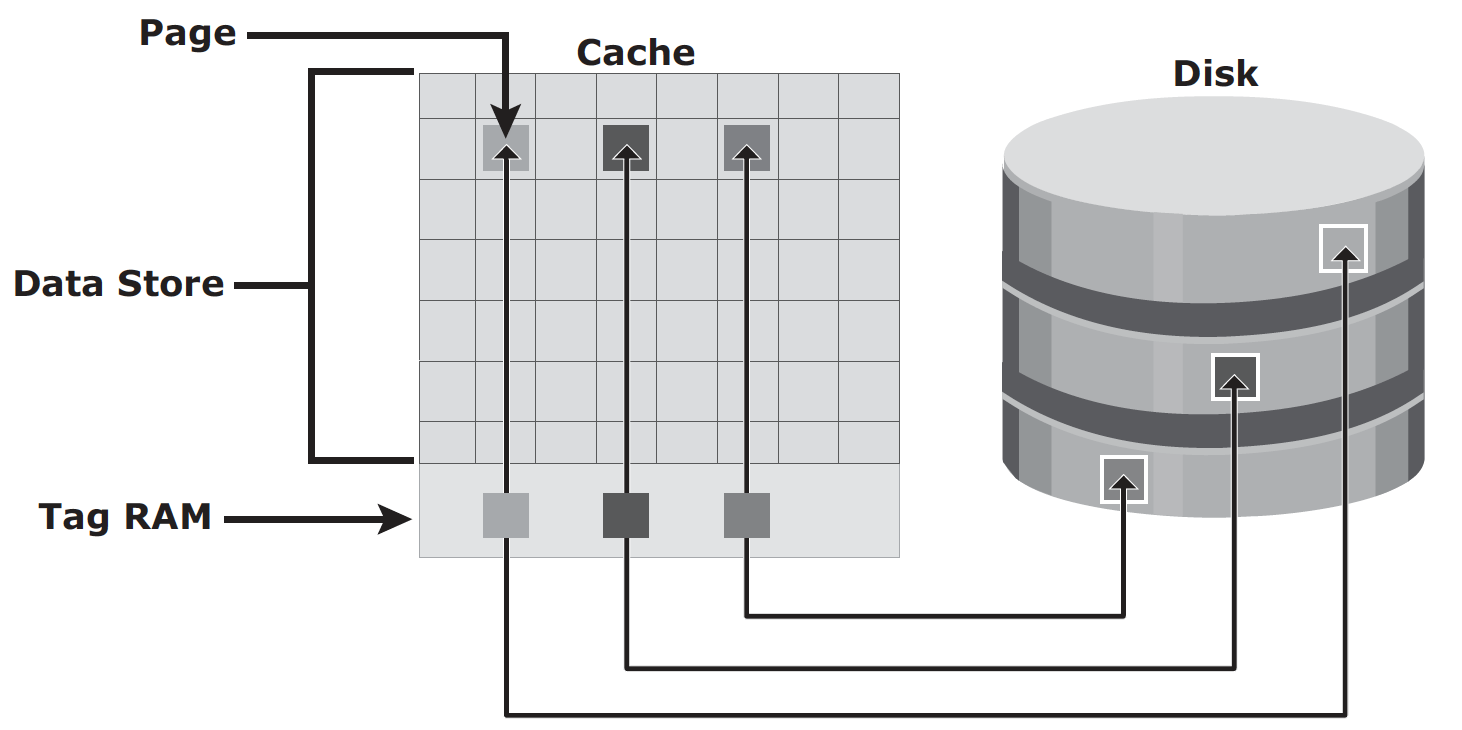
Page is the basic unit of cache, and the size of page is configured based on application I/O size. Cache consists of:
- data store: holds the actual data temporarily
- tag RAM: mainly serves three purposes:
- it tracks locations of data in cache and on disk;
- it maintains dirty bit flag to indicate whether data in cache has been committed to disk;
- it keeps time based information such as last access time, for cache management
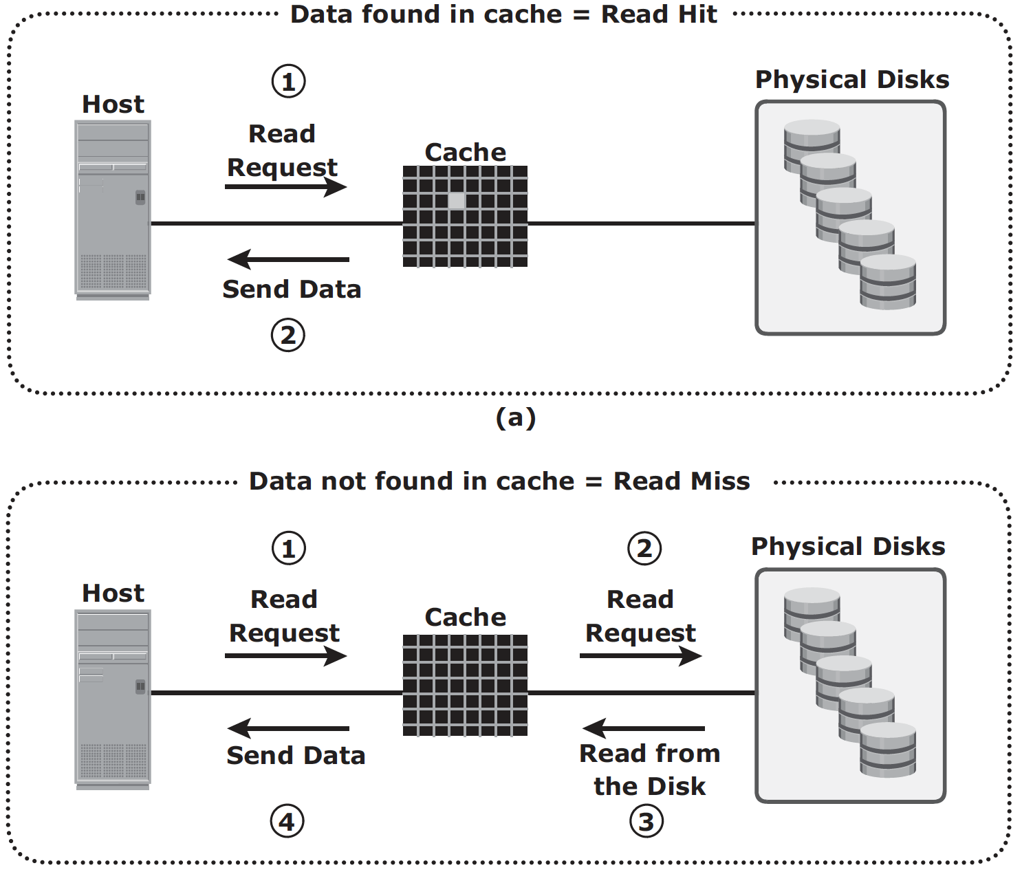
Read Operation with Cache: When host issues a read request, the storage controller reads the tag RAM first to determine whether required data is available in cache:
- Read cache hit: data is sent to host without any disk operation;
- Read cache miss: back end access the disk to retrieve the requested data. Data is then placed in cache and sent to host through front end.
Cache miss increases I/O response time, to increase read hit ratio, read-ahead algorithm can be used when read requests are sequential. In a sequential read request, a contiguous set of associated blocks is retrieved. Several other blocks that have not yet been requested by the host can be read from the disk and placed into cache in advance. When the host subsequently requests these blocks, the read operations will be read hits.
- Fixed prefetch – the intelligent storage system prefetches a fixed amount of data. It is most suitable when host I/O sizes are uniform.
- Variable prefetch, the storage system prefetches an amount of data in multiples of the size of the host request.
- Maximum prefetch limits the number of data blocks that can be prefetched to prevent the disks from being rendered busy with prefetch at the expense of other I/Os.
Write Operation with Cache: When an I/O is written to cache and acknowledged, it is completed in far less time (from the host’s perspective) than it would take to write directly to disk. Sequential writes also offer opportunities for optimization because many smaller writes can be coalesced for larger transfers to disk drives with the use of cache. Write operation with cache can be implemented in two ways:
- Write-back cache: Data is placed in cache and an acknowledgment is sent to the host immediately. Later, data from several writes are committed (de-staged) to the disk. Write response times are much faster because the write operations are isolated from the mechanical delays of the disk. However, uncommitted data is at risk of loss if cache failures occur.
- Write-through cache: Data is placed in the cache and immediately written to the disk, and an acknowledgment is sent to the host. Because data is committed to disk as it arrives, the risks of data loss are low, but the write-response time is longer because of the disk operations.
If the size of an I/O request exceeds the write aside size, writes are sent to the disk directly to reduce the impact of large writes consuming a large cache space. This is helpful where cache resources are constrained and cache is required for small random I/Os.
Cache space can be assigned in two ways:
- dedicated cache: separate sets of locations are reserved for read and write;
- global cache: user may specify percentage of cache for read and write based on application workload pattern; or the system set is dynamically.
Cache Management algorithm is used to determine when, and what pages of the cache need to be free up during maintenance. Most commonly used algorithms are:
- LRU (least recently used): assuming data not accessed for a while will not be requested by host any more;
- MRU (most recently used): assuming data recently accessed will not be requested by host again
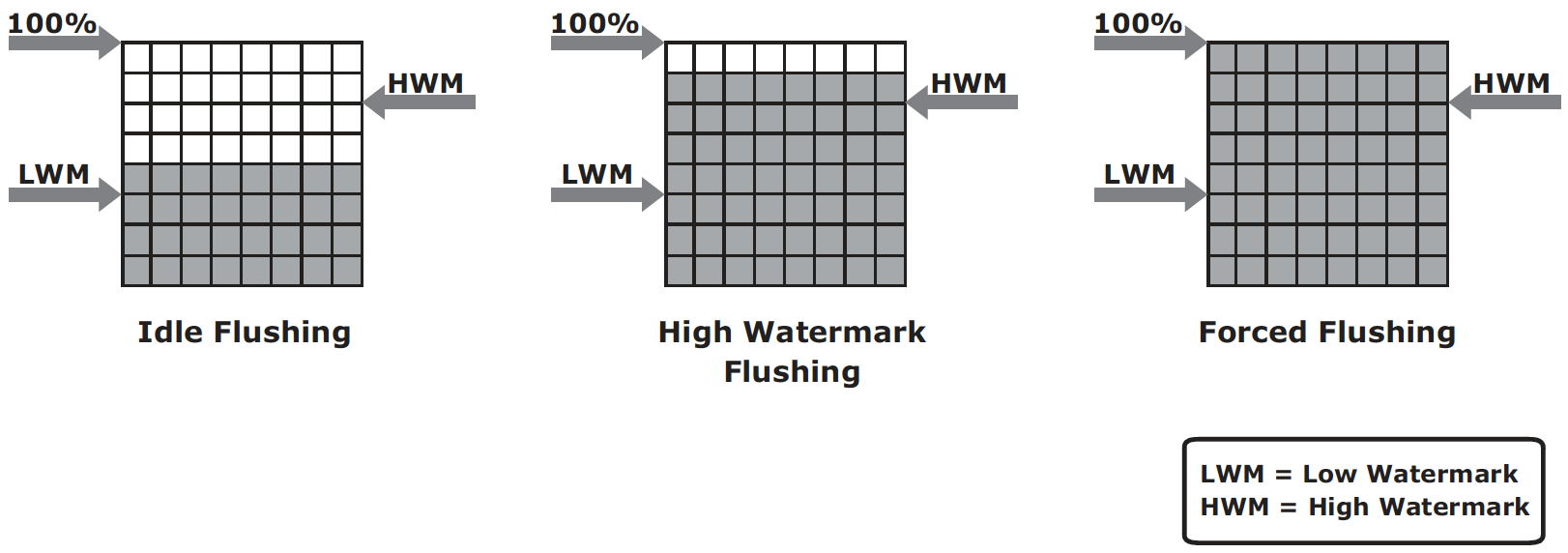
As cache fills, the storage system must take action to flush dirty pages by committing data from cache to disk. There are several triggers for cache management action:
- Idle flushing – occurs continuously at modest rate when cache utilization level is between high and low watermark;
- High watermark flushing – activated when utilization hits high watermark; and stops at low watermark; this has impact to I/O processing;
- Forced flushing – occurs in the event of large I/O burst when cache reaches 100% capacity; this significantly impacts I/O response time
Cache data protection is the mechanism to prevent losing uncommitted data held in cache. Common mechanisms are:
Cache mirroring – Each write to cache is held in two different memory locations on two independent memory cards. If a cache failure occurs, the write data will still be safe in the mirrored location and can be committed to the disk. The array operating environment needs to maintain cache coherency between the redundant memory locations. Read cache does not need mirroring.
Cache vaulting – In the event of server power failure, use battery power to write the cache content to the disk (vault drive). When power is restored, data from these disks is written back to write cache and then written to the intended disks.