NAS (network attached storage)
NAS server is dedicated to file-serving. NAS device runs its own specialized operating system that is optimized for file I/O, integrated hardware and software component that meets specific file-service needs, and performs file I/O better than a general-purpose server. NAS device can serve more clients than general-purpose servers and provide the benefit of server consolidation (centralized storage).
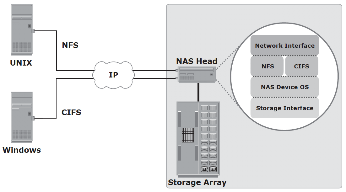
NAS uses network and file-sharing protocols to provide access to the file data. These protocols include TCP/IP for data transfer, and Common Internet File System (CIFS) and Network File System (NFS) for network file service.
Network File Sharing – user who creates a file determines the type of access to be given to other user. When multiple users try to access a shared file at the same time, a locking scheme is required to maintain data integrity and, at the same time, make this sharing possible. Examples of file sharing method (FTP, DFS, NFS, CIFS, P2P)
Components of NAS – NAS head (CPU, memory, NIC, optimized OS, ports, applications that supports CIFS/NFS) and Storage Array
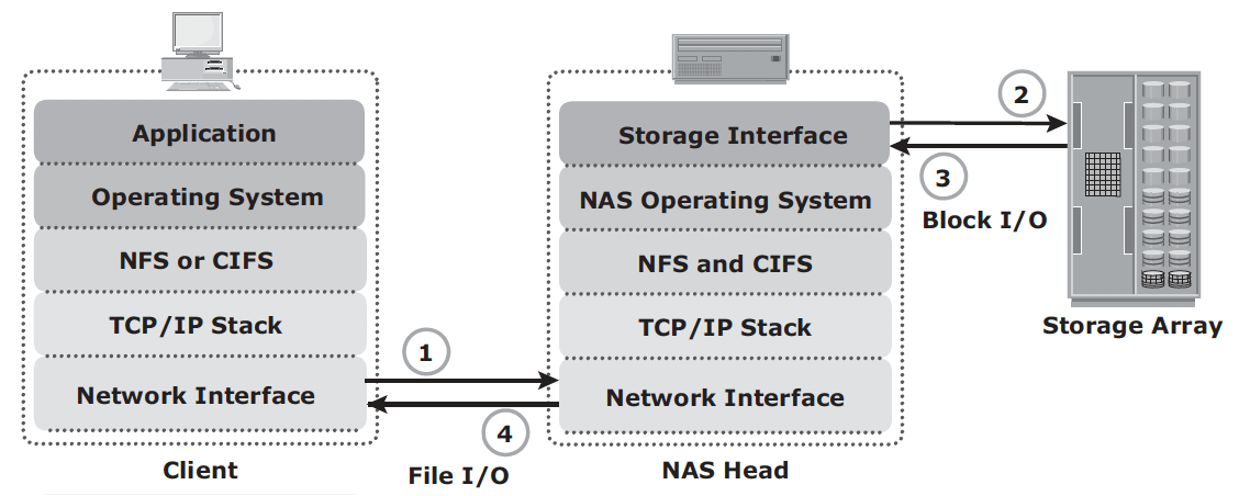
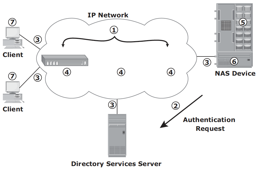
NAS I/O operation:
- Client packages an I/O request into TCP/IP and forwards it through network stack. NAS head receives this request from network;
- NAS head converts the I/O request into an appropriate physical storage request, which is a block-level I/O, and then performs the operation on the physical storage;
- When NAS head receives data from the storage array, it processes and repackages the data into an appropriate NFS/CIFS response;
- NAS head packages this response into TCP/IP again and forwards it to the client through the network
NAS implementation
Unified NAS – consolidate NAS-based and SAN-based data access within a unified storage platform and provides a unified management interface for managing both the environments.
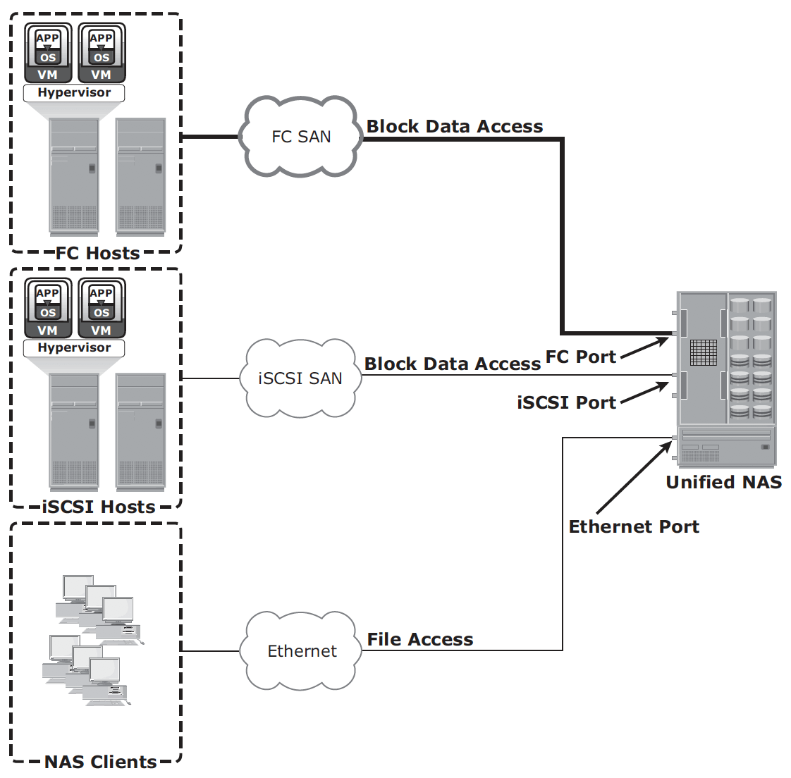
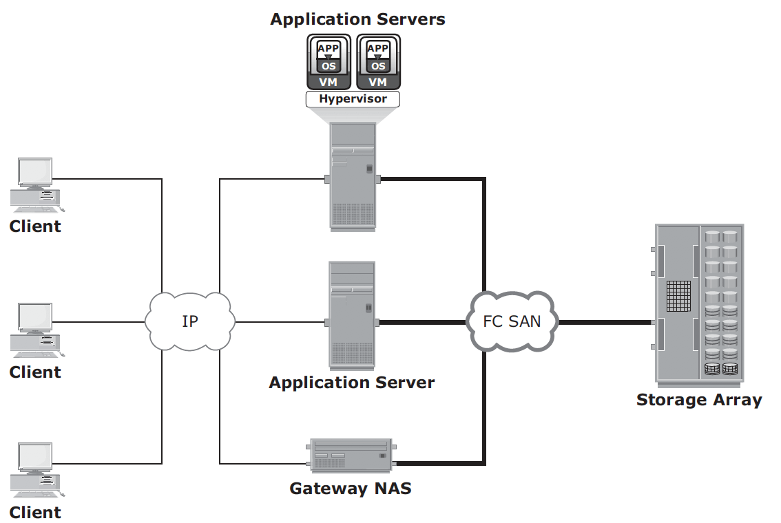
Gateway implementation – similar to unified NAS, the storage is shared with other applications that use block-level I/O. The gateway NAS is more scalable compared to unified NAS because NAS heads and storage arrays can be independently scaled up when required. For example, NAS heads can be added to scale up the NAS device performance.
When the storage limit is reached, it can scale up, adding capacity on the SAN, independent of NAS heads. Similar to a unified NAS, a gateway NAS also enables high utilization of storage capacity by sharing it with the SAN environment.
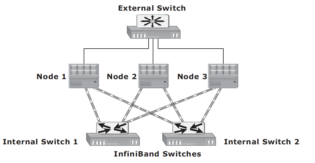
Scale-out NAS – enables grouping multiple nodes together to construct a clustered NAS system. A scaled-out NAS provides the capability to scale its resources by simply adding nodes to a clustered NAS architecture. The cluster works as a single NAS device and is managed centrally. Scaled-out NAS creates a single file system that runs on all nodes in the cluster. All information is shared among nodes, so the entire file system is accessible by clients connecting to any node in the cluster. Scale-out NAS stripes data across all nodes in a cluster along with mirror or parity protection. As data is sent from clients to the cluster, the data is divided and allocated to different nodes in parallel. When a client sends a request to read a file, the scale-out NAS retrieves the appropriate blocks from multiple nodes, recombines the blocks into a file, and presents the file to the client. As nodes are added, the file system grows dynamically and data is evenly distributed to every node. Each node added to the cluster increases the aggregate storage, memory, CPU, and network capacity. Hence, cluster performance also increases.
Scale-out NAS use separate internal and external networks for back-end and front-end connectivity, respectively. The internal network offers high throughput and low-latency and uses high-speed networking technology, such as InfiniBand or Gigabit Ethernet.
NFS protocol – originally based on UDP, uses RPC as a method of inter-process communication between two computers. NFS provides a set of RPCS to access remote file system for the following operations:
- Searching files and directories
- Opening, reading, writing to and closing a file
- Changing file attributes
- Modifying file links and directories
NFSv3 and earlier is stateless protocol. Each call provides a full set of arguments to access files on the server. NFSv3 is most commonly used version, based on UDP or TCP.
NFSv4 uses TCP and is based on stateful protocol design.
CIFS – a public, or open variation of SMB protocol. Filenames in CIFS are encoded using unicode characters. It is stateful protocol because the server maintain connection information regarding every connected client. If a network failure or CIFS server failure occurs, the client receives a disconnection notification. If application has embedded intelligence to restore the connection, then the storage solution is fault tolerant. If the embedded intelligence is missing, the user must take steps to reestablish the CIFS connection.
NAS Performance – network congestion is one of the most significant sources of latency in NAS environment. Other factors
- number of hops
- authentication with AD
- Retransmission – speed and duplex settings on the network devices and NAS heads must match
- Over-utilized routers and switches
- File system lookup and metadata request – deep directory structure could cause delay.
- Over-utilized NAS devices – client accessing multiple files can cause high utilization levels on a NAS device
- Over-utilized clients – if a client is busy itself, it requires a longer time to process the request and responses.
NFS server manages privilege and does not require username and password from the client at the time of mounting. CIFS share does require username and password.
Common network optimization practices for network contestion:
A VLAN is a logical segment of a switched network or logical grouping of end devices connected to different physical networks. The segmentation or grouping can be done based on business functions, project teams, or applications. VLAN is a Layer 2 (data link layer) construct and works similar to a physical LAN. A network switch can be logically divided among multiple VLANs, enabling better utilization of the switch and reducing overall cost of deploying a network infrastructure.
The broadcast traffic on one VLAN is not transmitted outside that VLAN, which substantially reduces the broadcast overhead, makes bandwidth available for applications, and reduces the network’s vulnerability to broadcast storms.
MTU setting determines the size of the largest packet that can be transmitted without data fragmentation. Path maximum transmission unit discovery is the process of discovering the maximum size of a packet that can be sent across a network without fragmentation. The default MTU setting for an Ethernet interface card is 1,500 bytes. A feature called jumbo frames sends, receives or transports Ethernet frames with an MTU of more than 1,500 bytes. The most common deployments of jumbo frames have an MTU of 9,000 bytes. However, not all vendors use the same MTU size for jumbo frames. Servers send and receive larger frames more efficiently than smaller ones in heavy network traffic conditions. Jumbo frames ensure increased efficiency because it takes fewer, larger frames to transfer the same amount of data. Larger packets also reduce the amount of raw network bandwidth being consumed for the same amount of payload. Larger frames also help to smooth sudden I/O burst.
The TCP window size is the maximum amount of data that can be sent at any time for a connection. For example, if a pair of hosts is talking over a TCP connection that has a TCP windows size of 64KB, the sender can send only 64KB of data and must then wait for an acknowledgement from the receiver. If the receiver acknowledges that all the data has been received, then the sender is free to send another 64 KB of data. If the sender receives an acknowledgment from the receiver that only the first 32 KB of data has been received, which can happen only if another 32 KB of data is in transit or was lost, the sender can send only another 32 KB of data because the transmission cannot have more than 64 KB of unacknowledged data outstanding.
In theory, the TCP window size should be set to the product of the available bandwidth of the network and the round-trip time of data sent over the network. For example, if a network has a bandwidth of 100 Mbps and the round-trip time is 5 milliseconds, the TCP window should be as follows:
100 Mb/s x .005 seconds = 524,288 bits or 65,536 bytes
The size of the TCP window fi eld that controls the fl ow of data is between 2 bytes and 65,535 bytes
Link aggregation is the process of combining two or more network interfaces into a logical network interface, enabling higher throughput, load sharing or load balancing, transparent path failover, and scalability. Due to link aggregation, multiple active Ethernet connections to the same switch appear as one link. If a connection or a port in the aggregation is lost, then all the network traffic on that link is redistributed across the remaining active connections.
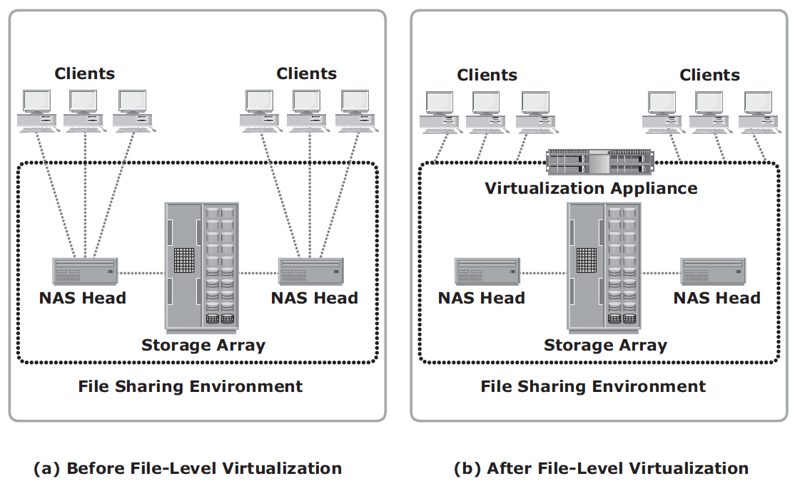
File-level virtualization
File-level virtualization eliminates the dependencies between the data accessed at the file level and the location where the files are physically stored. Implementation of file-level virtualization is common in NAS or file-server environments. It provides non-disruptive file mobility to optimize storage utilization.
It provides user or application independence from the location where the files are stored. File-level virtualization creates a logical pool of storage, enabling users to use a logical path, rather than a physical path, to access files. While the files are being moved, clients can access their files non-disruptively. Clients can also read their files from the old location and write them back to the new location without realizing that the physical location has changed. A global namespace is used to map the logical path of a file to the physical path names.
Object-based storage
In NAS, metadata are stored as part of the file distributed throughout the environment, which adds to the complexity and latency in searching and retrieving files. Object-based storage, on the other hand, stores file data in the form of objects based on its content and other attributes, rather than the name and location.
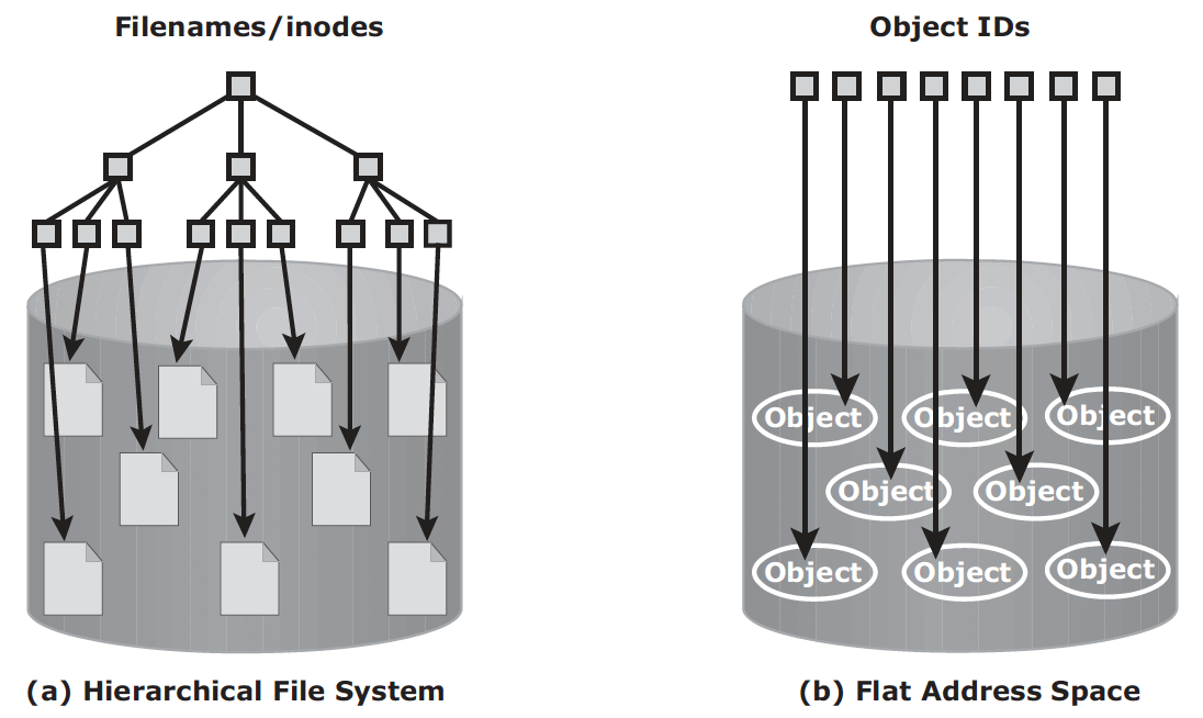
OSD – object-based storage devices, stores data in the form of objects using flat address space. There is no hierarchy of directories and file. Object is identified by objectID, which is usually generated using hash function.
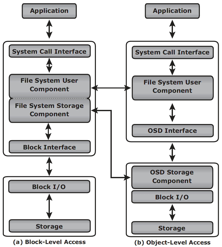
In block storage, when file system receives the IO from an application, the file system maps the incoming I/O to the disk blocks. The block interface is used for sending the I/O over the channel or network to the storage device. The I/O is then written to the block allocated on the disk drive. When an application accesses data stored in OSD, the request is sent to the file system user component. The file system user component communicates to the OSD interface, which in turn sends the request to the storage device. The storage device has the OSD storage component responsible for managing the access to the object on a storage device.
Benefit of object storage
- security and reliability: OSD can use special algorithm for strong encryption capacity. Request authentication is performed at the storage device rather than with an external authentication mechanism
- platform independence: standard web access via REST or SOAP
- scalability: Both storage and OSD nodes can be scaled independently in terms of performance and capacity
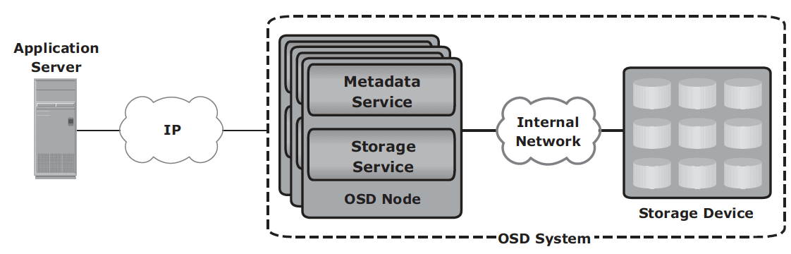
OSD components:
- nodes: a server with OSD operating environment to provide services to store, retrieve and manage data. Two key services are metadata service (generating objectID and maintaining the mapping between objectID and file) and storage service (manage a set of disks where data are stored).
- private network: provides node-to-node connectivity and node-to-storage connectivity.
- storage device
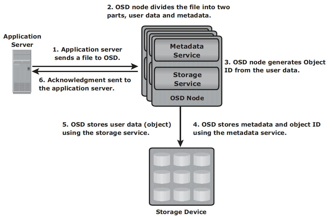
Storage mechanism
- The application server presents the file to be stored to the OSD node.
- The OSD node divides the file into two parts: user data and metadata.
- The OSD node generates the object ID using a specialized algorithm. The algorithm is executed against the contents of the user data to derive an ID unique to this data.
- For future access, the OSD node stores the metadata and object ID using the metadata service.
- The OSD node stores the user data (objects) in the storage device using the storage service.
- An acknowledgment is sent to the application server stating that the object is stored.
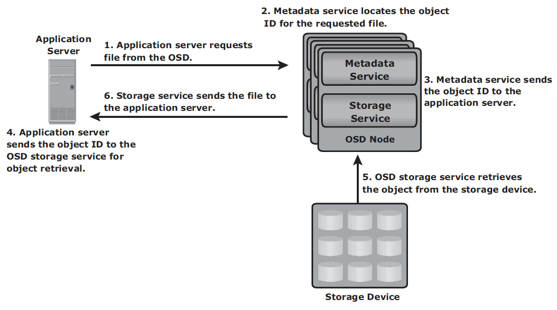
Retrieval mechanism
- The application server sends a read request to the OSD system.
- The metadata service retrieves the object ID for the requested file.
- The metadata service sends the object ID to the application server.
- The application server sends the object ID to the OSD storage service for object retrieval.
- The OSD storage service retrieves the object from the storage device.
- The OSD storage service sends the file to the application server.
OSD usage: data archival, especially long-term; and cloud storage, storage as service
CAS – content addressed storage, a special type of OSD designed for secure online storage and retrieval of fixed content. Data access in CAS differs from other OSD devices. In CAS, the application server access the CAS device only via the CAS API running on the application server. However, the way CAS stores data is similar to the other OSD systems.
CAS Use case
- Healthcare: storing patient studies – size of radiology study ranges from 15MB to more than 1GB. Newly acquired studies are retained for 60 days and moved to long term storage.
- Finance: storing financial records – bank stores images of cheques (~25KB each) for about 90 millions a month. Images are processed in transaction system for 5 days. For the next 60 days images are requested for verifications. After 60 days access requirements drop drastically. Retention policy manages life-cycle of the images.
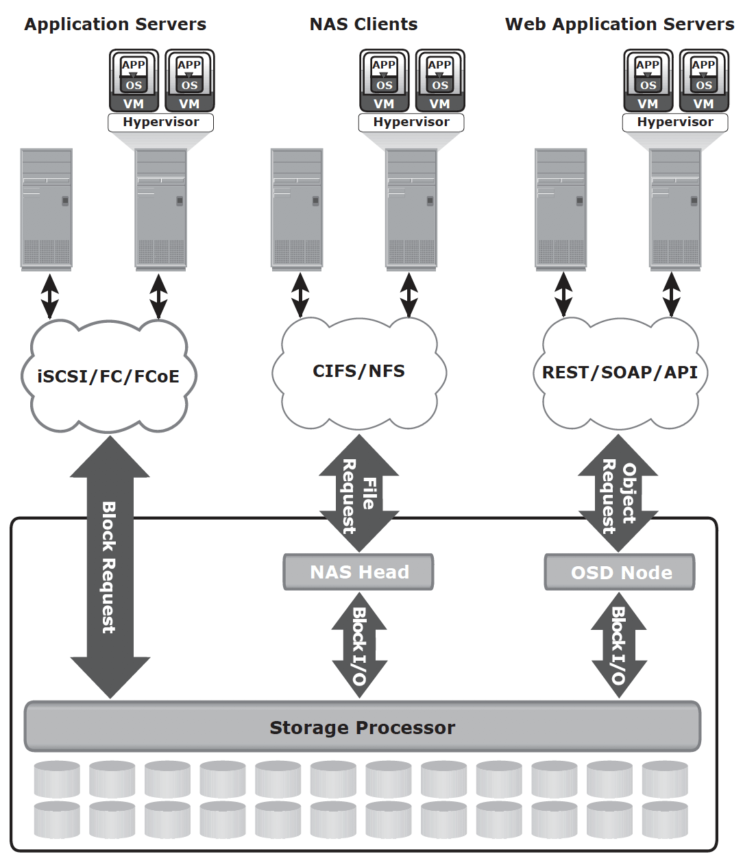
Unified storage
Components
- storage controller: The storage controller provides block-level access to application servers through iSCSI, FC, or FCoE protocols.
- NAS head: a dedicated file server that provides file access to NAS clients
- OSD node: accesses the storage through the storage controller using a FC or FCoE connection.
- Storage