Reading notes of “Docker DeepDive”.
Docker networking is backed by libnetwork, which is an implementation of Container Network Model (CNM), an open-source pluggable architecture designed to provide networking to containers. Libnetwork also provides native service discovery and basic container load balancing solution. Docker networking also involves some drivers that extend the CNM model with specific network topology implementation.
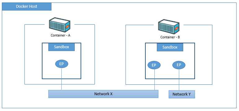
- Sandbox – an isolated network stack, including Ethernet interfaces, ports, routing tables, and DNS config, usually implemented through Linux namespace.
- Endpoints – behave like regular network adapters, and can only be connected to a single network at a time. It connects sandbox to network. Endpoint is implemented in veth pair in Linux.
- Networks – software implementation of an 802.1 bridge (aka switch). They group together, and isolate, a collection of endpoints that need to communicate.
Docker company separates network project out from its container project, as a plugin called libnetwork, which is developed in Golang and compliant to CNM. Libnetwork is the official implementation of CNM.
Libnetwork supports the following network modes:
| network mode | mechanism | use case |
| null | no network is provided to containers | quarantined environment for security |
| bridge | containers communicate with each other through bridge | containers needs to communicate with each other or with host service |
| host | process in container has access to host network stack and use host port | container needs to use host network stack (e.g. licence by mac address) |
| container | place containers in a single net namespace so they can communicate with each other as localhost | proxy, kubernetes |
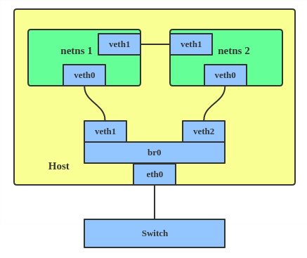
Linux veth comes in pairs to connect virtual network devices. For example, connect two net namespaces to allow intercommunication. Linux bridge is a virtual device, to connect two net namespaces.
Dockers ships with several built-in drivers, known as native drivers or local drivers, such as bridge, overlay and macvlan on Linux. There are also 3rd-party network drivers for docker (aka remote drivers).
Host network
In this mode libnetwork will not create network and net namespace for container. Container process shares the network configuration of the host, and therefore uses the ports on host. Other than network sharing, other aspects (e.g. process, file system, hostname, etc) are separated from host.
Bridge networks
This type of network only exist on a single Docker host and can only connect containers that are on the same host. The word bridge refers to 802.1d bridge (layer 2 switch), which is used to connect multiple network interfaces.
Every Docker host gets a default single-host network, called bridge on Linux. This is the network that all new containers will attach to by default.
Docker networks built with the bridge driver on Linux hosts are based on the linux bridge technology that has existed in the Linux kernel for a while. They’re high performance and extremely stable. Linux brctl tool can inspect the linux bridge.
Bridge networks allows container on the same host to communicate with each other. Port mapping allows network connectivity between container and host. Traffic hitting host port will be redirected to container port.
Multi-host overlays
Cross-host networking usually uses an overlay network, which builds a mesh between host and employs a large block of IP addresses within that mesh. A mesh network is a local network topology in which the infrastructure nodes connect directly, dynamically and non-hierarchically to as many other nodes as possible and cooperate with one another to efficiently route data from/to clients.
You can attach a service to overlay network, which spans across multiple Docker hosts so that containers on different hosts can communicate at layer 2. They are much better alternatives than bridge network for container-to-container communication. Overlay networking is very common due to its scalability.
The trick is basically the layer 2 frame of the overlay network is encapsulated into layer 3 datagram transmitted across underlay network, at layer 3. This is achieved through VXLAN tunnels, which allows you to create a virtual Layer 2 network on top of an existing Layer 3 infrastructure. VXLAN is an encapsulation technology that existing routers and network infrastructure just see as regular IP/UDP packets without issue.
To create the virtual Layer 2 overlay network, a VXLAN tunnel is created through the underlying Layer 3 IP infrastructure (aka underlay network). Each end of the VXLAN tunnel is terminated by a VXLAN Tunnel Endpoint (VTEP). It’s this VTEP that performs the encapsulation/de-encapsulation.
VXLAN networking
To accomplish overlay network across multiple hosts, a new network sandbox was created on each host. A sandbox is like a container, but instead of running an application, it runs an isolated network stack – one that’s sandboxed from the network stack of the host itself.
A virtual switch (aka virtual bridge) called Br0 is created inside the sandbox. A VTEP is also created with one end plumbed into the Br0 virtual switch, and the other end plumbed into the host network stack (VTEP). The end in the host network gets an IP address on the underlay network the host is connected to and is bound to a UDP socket on port 4789. The two VTEPs on each host create the overlay via a VXLAN tunnel.
Each container then gets its own virtual Ethernet (veth) adapter that is also plumbed into the local Br0 virtual switch.
Let’s go over an example in the following diagram, where container C1 with an overlay IP needs to communicate to another container C2, with a different overlay IP, sitting on a different node (Docker host). Each node has its own underlay IP.

IP communication details:
- C1 creates the IP datagram with destination IP (C2) and sends it over its veth interface, which is connected to the Br0 virtual switch on the host node.
- The virtual switch doesn’t know where to send the datagram, as it doesn’t have an entry in its ARP table that corresponds to the destination IP address. As a result, it floods the packet to all ports. The VTEP interface connected to Br0 knows how to forward the frame, so responds with its own MAC address.
- This is a proxy APR reply and results in the Br0 switch learning how to forward the packet. So it updates its ARP mapping the destination IP address to the MAC address of the local VTEP.
- The VTEP knows about C2 because all newly started containers have their network details propagated to the other nodes in the Swarm using the network’s built-in gossip protocol. When the packet arrives at node2
- The VTEP encapsulates the frame so it can be sent over the underlay transport infrastructure, by adding a VXLAN header to the Ethernet frame. The VXLAN header contains the VXLAN network ID (VNID) which is used to map frames from VLANs to VXLANs and vice versa.
- Each VLAN gets mapped to VNID, so that the packet can be de-encapsulated on the receiving end and forwarded to the correct VLAN. This is how network isolation is maintained. The encapsulation also wraps the frame in a UDP packet with the IP address of the remote VTEP on node2 in the destination IP field, and the UDP port 4789 socket information. The underlying network does not know that it is transporting data frames for the overlay network.
- When the packet arrives at node2, the kernel sees that it’s addressed to UDP port 4789. The kernel also knows that it has a VTEP interface bound to this socket. As a result, it sends the packet to the VTEP, which reads the VNID, de-encapsulates the packet, and sends it on to its own local Br0 switch on the VLAN that corresponds the VNID. From there it is delivered to container C2
Docker also supports Layer 3 routing within the same overlay network. For example, you can create an overlay network with two subnets, and Docker will take care of routing between them. Two subnets will require two virtual switches, Br0 and Br1, being created inside the sandbox, and routing happens by default.
Plugging into existing vLANs
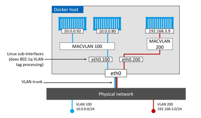
The built-in MACVLAN driver was created for onnect containerized apps to external physical network. A good example is partially containerized app, in which the containerized parts will need a way to communicate with the non-containerized parts still running on existing physical networks.
To connect the container interface through the host interface to an external network, the host NIC needs to be in promiscuous mode. For public cloud, this is most likely prohibited. For data centers, this depends on the network policy.
Docker MACVLAN driver is built on top of Linux kernel driver with the same name. As such, it supports VLAN trunking. This means we can create multiple MACVLAN networks and connect containers on the same Docker host to them.
For connectivity issues between containers, it’s worth checking both the daemon logs (on host) and container logs.
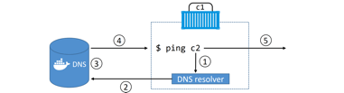
Service discovery
allows all containers and Swarm services to locate each other by name, as long as they are on the same network. This leverages Docker’s embedded DNS server as well as a DNS resolver in each container.
Each Swarm Service and standalone container started with the –name flag will register its name and IP address with the Docker DNS service.
This name resolution, however, only works within the same network.
It is also possible to configure Swarm services and standalone containers with customized DNS options in case embedded Docker DNS server cannot resolve a query (/etc/resolv.conf)
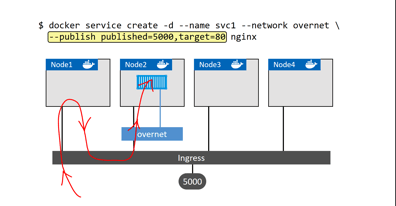
Ingress load balancing
Services published via ingress mode (by default, as opposed to host mode) can be accessed from any node in the Swarm, even nodes not running a service replica. Ingress mode uses a layer 4 routing mesh called the Service Mesh or the Swarm Mode Service Mesh.
Updates:
The most common network modes that I use are host and bridge. With host network mode, container exposes ports on the interface of the host machine. Containers talk to each other via that interface. With bridge network, containers have their own namespace of networking separate from the one from the interface of the hosts, with a bridge getting the two networks connected.
Reference
Docker Deep dive