
This post is a summary of VMware’s white paper Introduction to VMware vSphere.
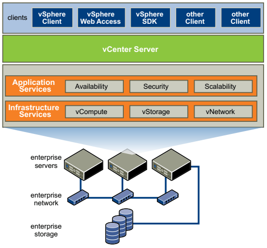
ESXi is the hypervisor (virtualization layer) on bare metal servers that abstracts processor, memory, storage and networking resources into multiple virtual machines. It was previously known as ESX and VMware discontinued ESX at version 4.1 so only ESXi is provided at and above version 5.0. vSphere is the platform to view, configure and manage the key aspects of virtualization, including:
- computing and memory resources (hosts, clusters and resource pools)
- storage resources (data stores)
- networking resources (networks)
- virtual machines
Under vSphere product family, vCenter Server is the central point for configuring, provisioning and managing the virtual environment. vShphere client is a client application to connect remotely to vCenter Server, or ESXi from any Windows PC. There is also vSphere Web Access for users from non-Windows environment.
For each aspects of virtualization, there is some vSphere features.
Computing
A host is a virtual representation of of the computing and memory resources of a physical machine running ESXi. When two or more physical machines are grouped to work and be managed as a whole, the aggregate computing and memory resources form a cluster. Physical machines can be dynamically added to or removed from a cluster. A cluster acts and can be managed as a single entity. It represents the aggregate computing and memory resources of a group of physical x86 servers sharing the same network and storage arrays. Computing and memory resources from hosts and clusters can be finely partitioned into a hierarchy of resource pools.
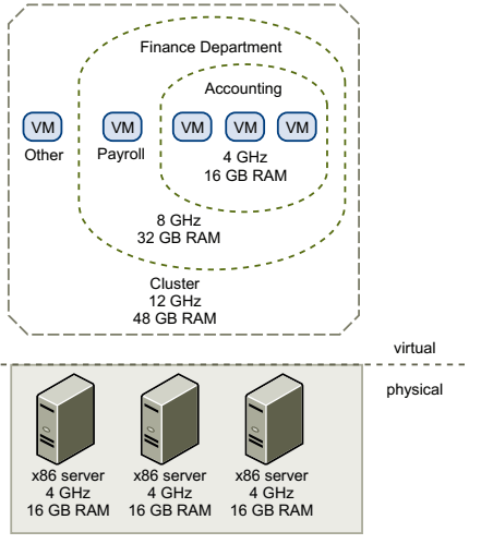
You can dynamically change resource allocation policies without shutting down the associated VMs. When reserved resources are not being used by a resource pool or a VM, the resources can be shared. This helps to maximize resource use while also ensuring that reservations are met and resource policies enforced.
ESXi provides a memory compression cache to improve VM performance when you use memory overcommitment. Memory compression is enabled by default. When a hosts memory becomes overcommitted, ESXi compresses virtual pages and stores them in memory. This is because accessing compressed memory is faster than accessing memory that has been swapped out to disk. Memory compression in ESXi allows you to overcommit memory without hindering performance. When a virtual page needs to be swapped, ESXi first attempts to compress the page. Pages that can be compressed to 2KB or smaller are stored in the VM’s compression cache, increasing the capacity of the host.
High Availability
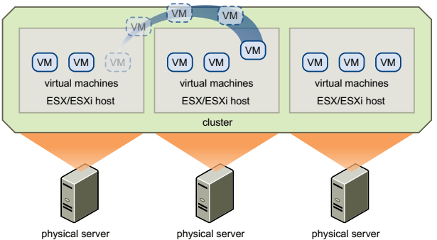
VMware vMotion enables the migration of running VMs from one physical server to another without service interruption. The effect is a more efficient assignment of resources across physical servers.
Storage vMotion enables the migration of VMs from one datastore to another datastore without service interruption. This allows administrators to off-load VMs from one storage array to another.
VMware DRS (distributed resource scheduler) helps you manage a cluster of physical hosts as a single compute resource. You can configure DRS to execute VM placement, VM migration, and host power actions. When you create a VM on a cluster, DRS places the VM in such a way as to ensure that load across the cluster is balanced, and cluster-wide resource allocation policies (e.g. reservations, priorities, and limits) are enforced. When you add a new physical server to a cluster, DRS enables VMs to immediately take advantage of the new resources. When a VM is powered on, DRS performs an initial placement of the VM on a host. As cluster conditions (e.g. load and available resources) change over time, DRS migrates (using vMotion) VMs to other hosts as necessary.
When DPM (distributed power management) is enabled, the system compares cluster-level and host-level capacity to the demands of VMs running in the cluster. If the resource demands of the running VMs can be met by a subset of hosts in the cluster, DPM migrates the VMs to this subset and powers down the hosts that are not needed. When resource demands increase, DPM powers these hosts back on and migrates the VMs to them. This dynamic cluster right-sizing that DPM performs reduces the power consumption of the cluster, without sacrificing VM performance or availability.
Storage I/O control congestion management allows cluster-wide storage I/O prioritization and enables administrator to set congestion thresholds for I/O shares.
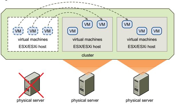
VMware HA enables quick automated restart of virtual machines on a different physical server within a cluster if a host fails. HA monitors all physical hosts in a cluster and detects host failures. An agent placed on each physical host maintains a heartbeat with the other hosts in the resource pool. Loss of a heartbeat initiates the process of restarting all affected VMs on that host. HA also provides a VM monitoring feature that monitors the status of VM in an HA cluster. If a VM does not generate heartbeats within a specified time, VM monitoring identifies it as having failed and restarts it. HA is configured centrally through vCenter Server and once configured, it operates continuously and in a distributed manner on every ESXi host without needing vCenter Server to stay up.
VMware vLockstep technology and VMware Fault Tolerance provides continuous availability by protecting a VM with a shadow copy that runs in virtual lockstep on a separate host. Inputs and events performed on the primary VM are recorded and replayed on the secondary VM to ensure identical state. The secondary VM in virtual lockstep can take over execution at any point without interruption or loss of data.
Storage
Datastores are virtual representations of combinations of underlying physical storage resources in the data center. These physical storage resources include:
- Local SCSI, SAS, or SATA disks attached to the physical machines
- Fibre Channel or iSCSI SAN disk arrays
- Network Attached Storage (NAS) arrays
Storage subsystem appears as a virtual SCSI controller connected to one or more virtual SCSI disks. These virtual controllers (BusLogic Parallel, LSI Logic Parallel, LSI Logic SAS and VMware Paravirtual) are the only types of SCSI controllers that a VM can see and access. The virtual SCSI disks are provisioned from datastore. This datastore abstraction is a model that assigns storage space to VMs while insulating the guest from the complexity of the underlying physical storage technology. The guest VM however, is not exposed to Fibre Channel SAN, iSCSI SAN, direct attached storage or NAS.
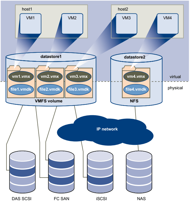
Each datastore is a VMFS volume on a storage device. Datastore can span multiple physical storage subsystems. A single VMFS volume can contain one or more LUNs from a local SCSI disk array on a physical host, a Fibre Channel disk farm, or iSCSI SAN disk farm. New LUNs added to any of the physical storage subsystems are detected and made available to all existing new datastores. Storage capacity on a previously created datastore can be extended without powering down physical hosts or storage subsystems. If any of the LUNs within a VMFS volume fails, only VMs that use that LUN are affected.
Each VM is stored as a set of files in a directory in the datastore. The disk storage associated with each VM is a set of files within the guest’s directory. You can operate on the guest disk storage as an ordinary file, which can be copied, moved, or backed up. New virtual disks can be added to a virtual machine without powering it down. In that case, a virtual disk file (.vmdk) is created in VMFS to provide new storage for the added virtual disk
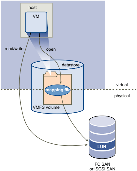
VMFS is a clustered file system that leverages shared storage to allow multiple physical hosts to read and write the same storage simultaneously. VMFS provides on-disk locking to ensure that the same virtual machine is not powered on by multiple servers at the same time. If a physical host fails, the on-disk lock for each VM is released so that VMs can be restarted on other physical hosts. VMFS also features failure consistency and recovery mechanisms, such as distributed journaling, a failure-consisten VM I/O path, and VM state snapshots. These mechanisms can aid quick identification of the cause and recovery from VM, physical host and storage subsystem failures. VMFS also supports raw device mapping (RDM), which is a mechanism for a VM to have direct access to a LUN on the physical storage subsystem (Fibre Channel or iSCSI only). An RDM is a symbolic link from a VMFS volume to a raw LUN. The mapping makes LUNs appear as files in a VMFS volume. The mapping file, not the raw LUN, is referenced in the VM configuration. When a LUN is opened for access, the mapping file is read to obtain the reference to the raw LUN. Thereafter, reads and writes go directly to the raw LUN rather than going through the mapping file.
Networking
Each VM has one or more vNICs (virtual network interface cards). The guest OS and application program communicate with a vNIC through either a commonly available device driver or a VMware device driver optimized for the virtual environment. In either case, communication in the guest OS occurs just as it would with a physical device. On the network, the vNIC responds to standard Ethernet protocol as would a physical NIC. An outside agent does not detect that it is communicating with a virtual machine.
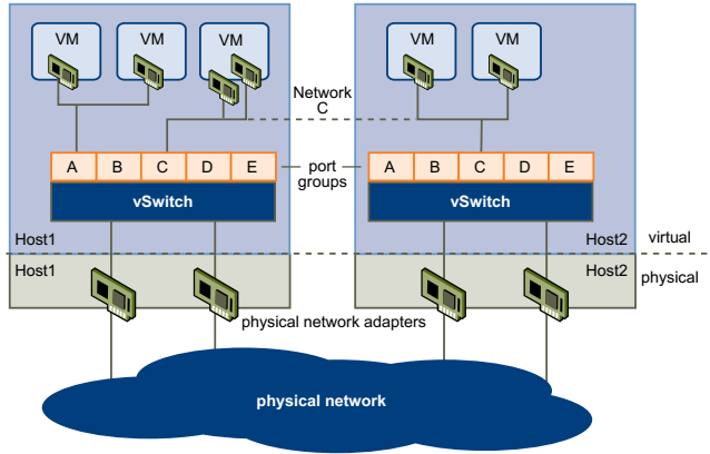
A virtual switch (vSwitch) works like a layer 2 physical switch. Each server has its own virtual switches. One one side of the virtual switch are port groups that connect to virtual machines. On the other side are uplink connections to physical Ethernet adapters on the physical server where the virtual switch resides. VMs connect to the outside world through the physical Ethernet adapters that are connected to the virtual switch uplinks. A virtual switch can connect its uplinks to more than one physical Ethernet adapter to enable NIC teaming.
Port group is a unique concept in the virtual environment. A port group is a mechanism for setting policies that govern the network connected to it. A vSwitch can have multiple port groups. A VM connects its vNIC to a port group instead of to a particular port on the vSwitch, for better network segmentation.
A vNetwork Distributed Swtich (vDs) function as a single virtual switch across all associated hosts. This functionality allows VMs to maintain consistent network configuration as they migrate across multiple hosts. Like vSwitch, each VDS is a network hub that VMs can use and it can route traffic internally between VMs or link to an external network by connecting to physical Ethernet adapters. Each vDS can also hae one or more dvPort groups assigned to it. dvPort groups aggregate multiple ports under a common configuration and provide a stable anchor point for VMs connecting to labeled networks.
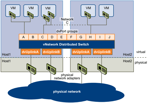
When network resource management is enabled, vDS traffic is divided into six network resource pools: FT traffic, iSCSI traffic, vMotion traffic, management traffic, NFS traffic, and VM traffic. You can control the priority of each of these network resource pools.
vCenter
vCenter Server provides centralized managed for data centers. It communicates with the ESXi host agent through the VMware vSphere API. When you first add a host to vCenter Server sends a vCenter Server agent to run on the host. The vCenter Server agent acts as a small vCenter Server to perform many fundamental management functions.