
What layer model works the best? Back in university my textbook was based on OSI 7-layer model. It is rigorously defined and often used in academics. When it comes to day-to-day operation, the 5-layer TCP/IP model is more useful. It combines Application, Presentation and Session layers in OSI model into a single Application layer.
| Layer | Name | Protocol | Protocol Data Unit | Addressing | Device | Description |
|---|---|---|---|---|---|---|
| 5 | Application | HTTP, FTP, etc | Message | N/A | N/A | |
| 4 | Transport | TCP and UDP | Segment | Port Number | Gateway | Sort out which application on the same host receives incoming data |
| 3 | Network | IP | Datagram | IP address | Router and (layer-3) switch | Allows devices across different networks to talk to each other |
| 2 | Data Link | Ethernet, WiFi | Frame | MAC address | Bridge and (layer-2) Switch | Defines common way of interpreting signals so devices in the network can communicate |
| 1 | Physical | 10baseT, 802.11 | bit | N/A | Hub | Hardware: cables, signal connector |
Physical Layer
Crosstalk – electrical pulse on one wire is accidentally detected on another wire. This was a common challenge when the industry started. The most common cable is UTP (Unshielded Twisted Pair) cable such as Cat 5, Cat 5e cables.
Hub – a physical layer device that allow for connectivity from many computers at once. It is up to each device to determine if incoming data is for them, or to ignore it. Because this slows down transmission, hubs are hardly used any more.
Collision domain – A network segment where only one device can communicate at a time. The device sending signal is occupying the entire media, within its time-sharing window. All devices connected to a hub are in the same collision domain. Ethernet nodes use CSMA/CD to detect collisions and re-transmit when the wire becomes available again.
Wireless Channels – individual, smaller sections of the overall frequency band used by a wireless network. Collision is very common in wireless communication. So the channel selection should minimize collision.
Data Link Layer
In a LAN, NICs talk to each other via MAC address (first 3 octets is organization unique identifier; the last 3 octets are assigned by vendor). Two NICs communicate through twisted pair cable in one of the following modes:
- Simplex: data is sent in one directly only;
- Half duplex: one line and transmission in each direction takes turns;
- Full duplex: two lines, one for each direction, simultaneous;
Network Switch – connects to many devices as well but it determines which device the data is intended for and only send that data to that device. Switch is a layer-2 device. (However today as a network device, many switches have layer-3 capability so it is important to be specific when talking about switch)
Ethernet Frame Format
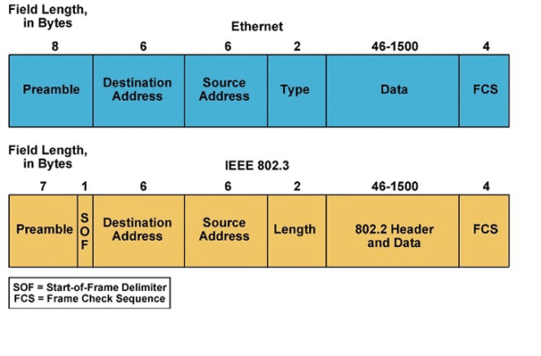
Ethernet address types:
- Unicast address: points to one receiving end; it contains a unique MAC address the frame is intended for;
- Multicast address: multicast frame is identified by FF as the first 8-bit, followed by a 4-bit flag field, a 4-bit scope field, and a 112-bit group ID.
- Broadcast address: for special destination such as ARP; it contains all Fs in the destination address.
Ethernet frame types include, but not limited to:
- Ethernet II frame (most common type in use today used directly by the Internet Protocol)
- Novell raw IEEE 802.3 non-standard variation frame
- IEEE 802.2 Logical Link Control (LLC) frame
- IEEE 802.2 Subnetwork Access Protocol (SNAP) frame
Virtual LAN – any broadcast domain that is partitioned and isolated in a computer network at the data link layer. It is a technique that allows you to have multiple logical LANs operating on the same physical equipment, to segregate traffic.
Network Layer
Router connects between LANs. A router needs at least two NICs. The steps to route are:
- Receive data packet
- Examines destination IP
- Look up IP destination network in routing table
- Forward traffic to destination;
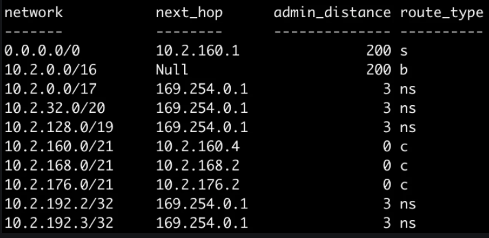
Routing can be complex but it is mostly handled by ISPs now. A routing table may have millions of rows (use route command to check). Here is an example of routing tables.
Autonomous system – a collection of networks that fall under the control of a single network operator (i.e. large corporation)
Routing protocol – specifies how routers communicate with each other, distributing information that enables them to select routes between any two nodes on a computer network. Interior Gateway Protocols are used by routers to share routing information within a single autonomous system. Exterior Gateway protocols are used across autonomous system.
- Interior Gateway Protocol (link-state routing): OSPF, IS-IS
- Interior Gateway Protocol (distance-vector): RIP, RIPv2, IGRP
- Exterior Gateway Protocol: BGP (Border Gateway Protocol) – allows routers (e.g. Internet) to learn from each other about the most optimal paths to forward traffic.
IP datagram
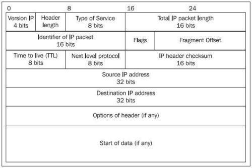
An IP datagram contains a lot more compared to Ethernet frames. One place called type of service field (8-bits) specifies priority. QoS technologies are mostly built on this field, to allow routers to determine which datagram is more important.
IP Fragmentation: an Internet Protocol (IP) process that breaks packets into smaller pieces (fragments), so that the resulting pieces can pass through a link with a smaller maximum transmission unit (MTU) than the original packet size. The fragments are reassembled by the receiving host. If a receiving host receives a fragmented IP packet, it has to reassemble the packet and pass it to the higher protocol layer. Reassembly is intended to happen in the receiving host but in practice it may be done by an intermediate router, for example, network address translation (NAT) may need to reassemble fragments in order to translate data streams.
IP address class
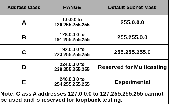
Non-routable IPv4 address spaces belong to no one. Any one can use them in their private network:
- 192.168.0.0/16
- 172.16.0.0/12
- 10.0.0.0/8
Subnetting – splitting large network into smaller ones. Incorrect subnetting setups are a common problem you might run into as an IT support. Each subnet has their ingress routers, subnet ID and subnet mask.
CIDR is a better way to describe subnet because router only need one entry in their routing table to know where to deliver the traffic.
NAT allows communicate between non-routable addresses.
ARP (address resolution protocol) table – maps IP address to MAC address. It is kept on each device (run arp -a to check) and expires after short period of time.